3.5.Pipelined Datapath and Control
\(3.5.\)Pipelined Datapath and Control
1.Some point
All the instructions go from left to right through the datapath except the write-back stage and the selection of the next value of PC, and they never move backward.
- So the first right-to-left flow of data can lead to data hazards while the second leads to control hazards.
One way to show what happens in pipelined execution is to pretend that each instruction has its own datapath, and then to place these datapaths on a timeline to show their relationship:
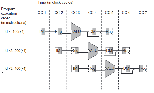
All instructions advance during each clock cycle from one pipeline register to the next.
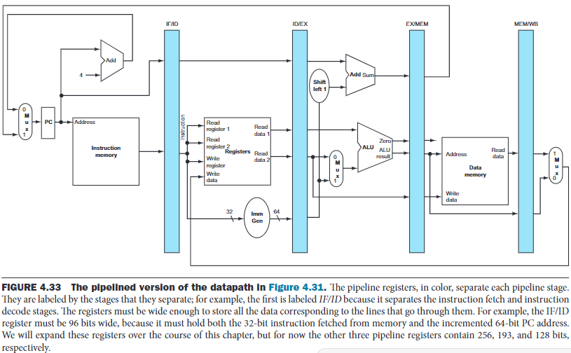
2.Pipeline registers
A separate pipeline register is redundant to the state that is updated. For example, a load instruction will place its result in one of the 32 registers, and any later instruction that needs that data will simply read the appropriate register.
- Every instruction updates PC, and the PC can be thought of as a pipeline register: one that feeds the IF stage of the pipeline.
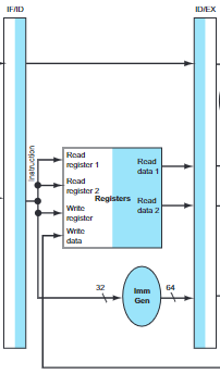
We use the command ld to illustrate the pipe stage
that is active in each stage:
- Instruction fetch: The PC is saved in the IF/ID pipeline register in case it's needed later for an instruction. This stage occurs before the instruction is identified.
The computer cannot know which type of instruction is being fetched, so it must prepare for any instruction, passing potentially needed information down the pipeline.
- Instruction decode and register file read: Both the two read value and sign-extended immediate are stored in the ID/EX pipeline register, along with PC address.
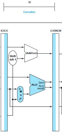
- Execute/address calculation: It reads the information from the ID/EX pipeline register and add then using ALU. The result is placed in EX/MEM pipeline register.
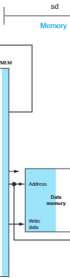
- Memory access: It uses the data from EX/MEM register and loads the data into MEM/WB pipeline register.
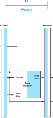
- Write back: There's nothing to do in this stage.
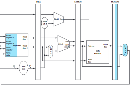
From the analysis above, we can get some key point:
The information must be placed in a pipeline register, otherwise, the information is lost when the next instruction enters that pipeline stage.
Each logical component of the datapath(ALU, data memory, etc), can be used only within a single pipeline stage. That is, each pipeline register can only be used by one phase in one clock cycle, which ensures that no more than one instruction can access the same hardware resources simultaneously in one clock cycle, thus avoiding structural dangers.
We know that the instruction in IF/ID pipeline register supplies
the writer register number, but the instruction fetch procedure occurs
after the ld instruction(because it is conducted before an
instruction is identified, so only when we complete the ld
instruction will this step be done)! Hence, we need to preserve
the distination register number in the ld
instruction. The ld must pass the register number
from ID/EX through EX/MEM to the MEM/WB pipeline register for use in the
WB stage.
3.Data hazards & forwarding
\(a.\)Data hazards
\(b.\)Detact hazards
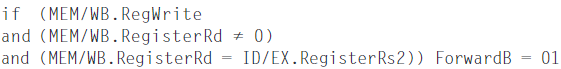
We first introduce a notation: we use "ID/EX.RegisterRs1" to refer to the number of 1 register whose value is found in the pipeline register ID/EX.
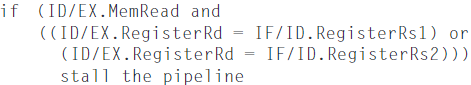
Using this notation, the two pairs of hazard conditions are:
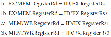
- The
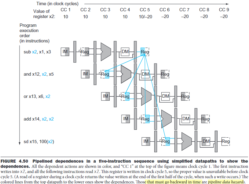
sub-andis a type 1a hazard:
\[ MEM/WB.RegisterRd=ID/EX.RegisterRs2=x2 \]
The
sub-oris a type 2a hazard.There's no data hazard between
subandsdbecausesdreadsx2the clock cycle aftersubwritesx2.
Pay attention to the clock cycle, not the name!!!
One way to detact the hazards is simple check if the
RegWrite signal is active. This can be done by
examing the WB control field of the pipeline
register during the EX and MEM
stages.
Recall that RISC-V requires that
x0is taken as an oprand value of 0, if an instruction in the pipeline hasx0as its destination, we want to avoid forwarding its possibly nonzero value.
\(c.\)Solution
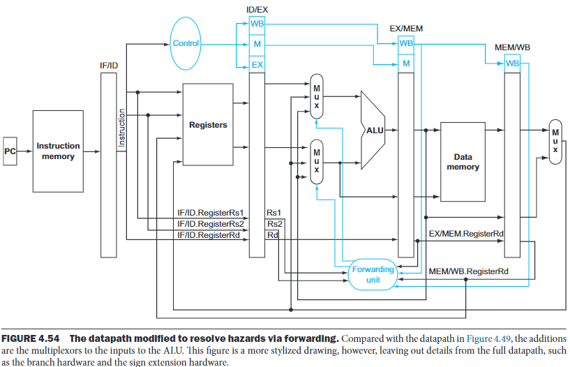
If we can take the inputs to the ALU from any pipeline register rather than just ID/EX, then we can forward the correct data.
By adding multiplexors to the input of the ALU, and with the proper controls, we can run the pipeline at full speed in the presence of these data hazards:
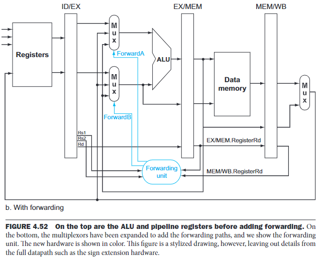
Before forwarding, the ID/EX register has no need to include space to hold the rs1 and rs2 fields, so they are added to ID/EX.
\(d.\)Detailed detection & resolution
EX hazard:
- If there's a write operation and a load operation at the same time, and the loaded object is under writting, then there's an EX hazard:
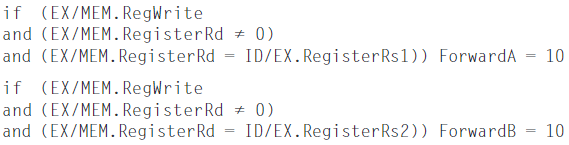
This case forwards the result from the previous instruction to either input of the ALU instead of the pipeline register EX/MEM
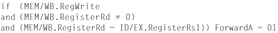
MEM hazard
- If the writting part is just loaded.
What happens when a register is read and written in the same clock cycle? We assume that the write is in the first half of the clock cycle and the read is in the second half, so the read delivers what is written. As is the case for many implementations of register files, we have no data hazard in this case.
As mentioned above, there is no hazard in the WB stage, because we assume that the register file supplies the correct result if the instruction in the ID stage reads the same register written by the instruction in the WB stage.
One complication occurs when we all read and write to a same register:
1 | add x1 x1 x2 |
In this case, the result should be forwarded from the MEM stage, because the MEM stage is the more recent result. Thus, the control for the MEM should be:
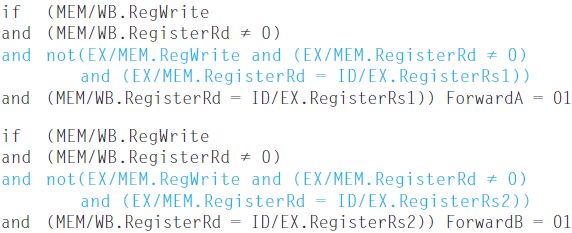
Why
not EX/MEM.RegisterRd = ID/EX.RegisterRs1? Because if this is true, then the instruction of EX/MEM should be written back into the register(because it's the most current), and it will cover the result of MEM/WB. So we take EX/MEM first.
\(e.\)Stalls
One case where forwarding cannot help is when an instruction tries to read a register following a load instruction that writes the same register:
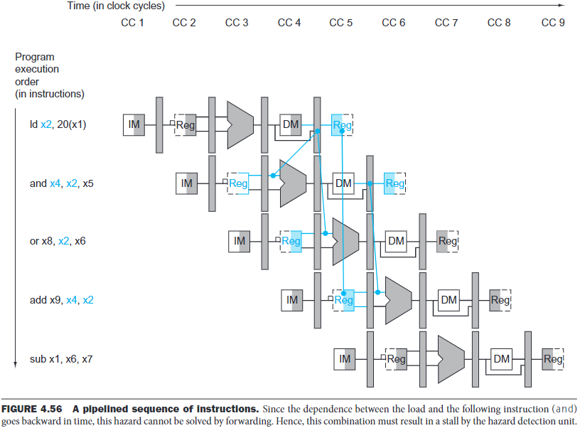
The RAM is used by
addbefore it's updated, and it won't be updated until thelwends. Since it must be used in the first step, forwarding cannot help.
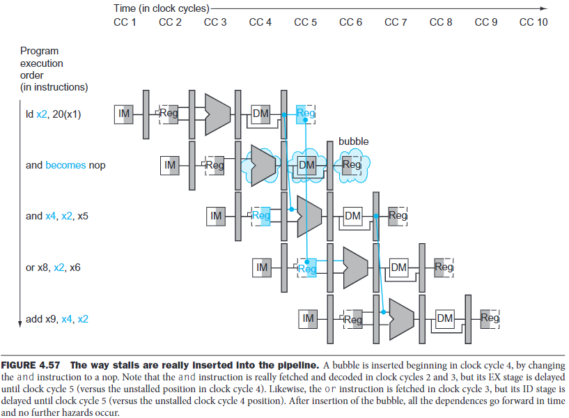
Hence, we also need a hazard detection unit. It operates during the ID stage so that it can insert the stall between the load and the instruction depentent on it:
- If it's in a load process, and the being-loaded object involves in other process.
If the instruction in the ID stage is stalled, then the instruction in the IF stage must also be stalled, or we will lose the fetch of instruction. Therefore, the instruction in the IF stage will continue to be read using the same PC. The EX stage must also be doing something, so we let it execute instructions that have no effect: nops.
Deasserting all seven control signals(setting them to 0) in the EX, MEM, WB stages will create a nop instruction:
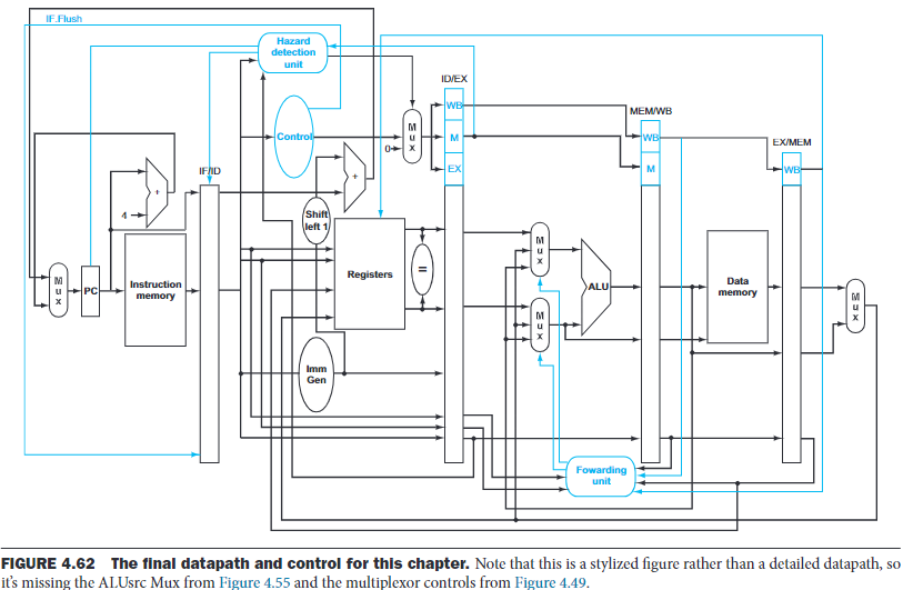
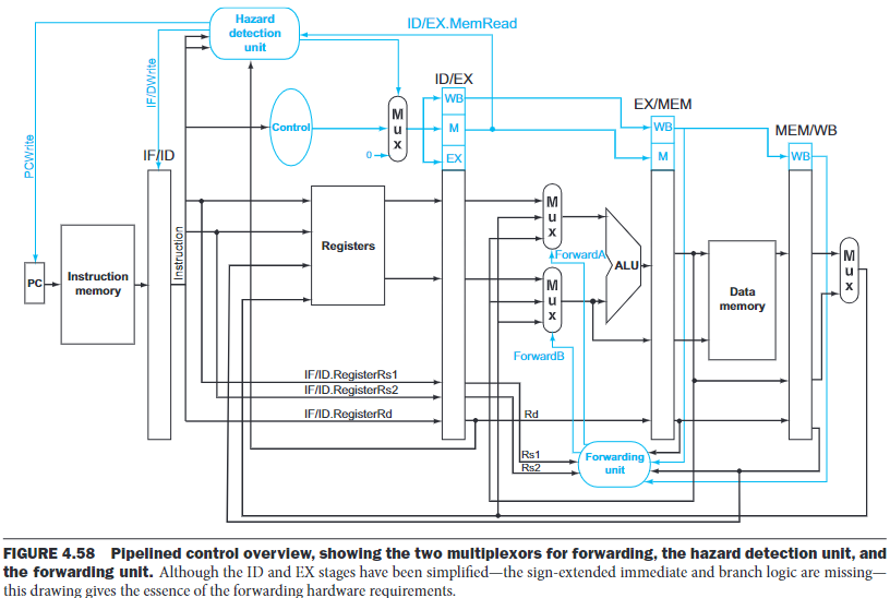
The forwarding unit controls the ALU multiplexor s to replace the value from a general-purpose register with that in the pipeline register.
The hazard detection unit controls the writing of the PC and IF/ID registers plus the multiplexor that choose between the real control values and all 0s.
4.Control hazards
\(a.\)Assume branch not taken
We can assume the branch is not taken. If the condition branch is taken instead, the instructions that are being fetched and decoded must be discarded.
To discard instructions, we merely change the original control values to 0s. Notice that we must also change the three instructions in the IF, ID and EX stages when the branch reaches the MEM stage, which is called flush.
To flush instructions in the IF, we add a control line called IF.Flush, it zeros the instruction field of the IF/ID pipeline register.
\(b.\)Reducing the delay of branches
One way to improve conditional branch performance is to reduce the cost of taken branch. We have assumed that the next PC for a branch is selected in the MEM stage, but if we move the conditional branch execution earlier in the pipeline, then fewer instructions need be flushed.
Moving the branch decision up requires two actions to occur earlier: computing the branch target address and evaluating the branch decision.
Moving up the address calculation is easy, we can move the branch adder from EX stage to ID stage.
The harder part is branch decision itself. We must deal with two complicate factors:
The introduction of equlity test unit.
Because the value in a branch comparison is needed during ID but may be produced later in time, it is possible that a data hazard can occur and a stall will be needed.
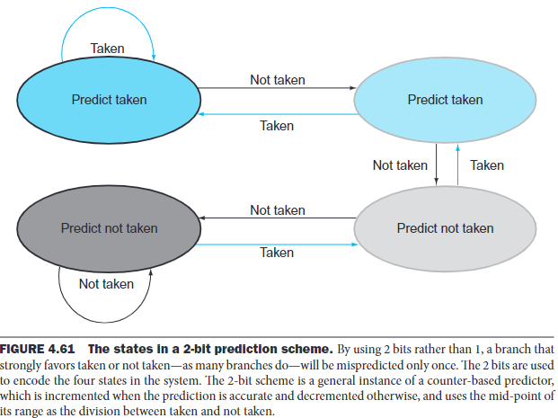
5.Dynamic branch prediction
- This method looks up the address of the instruction to see if the conditional branch was taken the last time this instruction was executed, and, if so, to begin fetching new instructions from the same place as the last time.
One implementation of this approach is a branch prediction buffer or branch history table. A branch prediction buffer is a small memory indexed by the lower portion of the address of the branch instruction. The memory contains a bit that says whether the branch was recently taken or not.
- Fetching begins in the predicted direction. If the predition turns out to be wrong, the incorrectly predicted instructions are deleted, the predition bit is inverted and stored back, and the proper sequence is fetched and executed.
To improve the accuracy, the 2-bit prediction schemes are often used. In a 2-bit scheme, a prediction must be wrong twive before it is changed: