4.5.Pipelined Y86-64 Implementations
\(4.5.\)Pipelined Y86-64 Implementations
1.SEQ+ Rearranging the Computation Stages
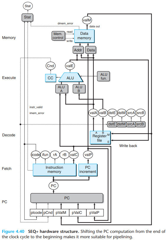
We slightly rearrange the order of the five stages in SEQ so that the PC update stage comes at the beginning of the clock cycle, rather than at the end. We refer to this modified design as SEQ+.
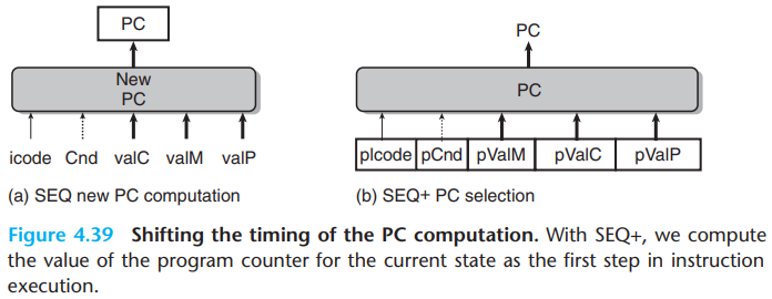
The old SEQ computes the PC register based on the values of signals computed during the current clock cycle.
While with SEQ+, we create state registers to hold the signals computed during an instruction. Then as the new clock cycle begins, the values propagate through the exact same logic to compute the PC for the now-current instruction.
In SEQ+, there is no hardware register storing the program counter. Instead, the PC is computed dynamically based on some state information stored from the previous instruction.
2.Inserting Pipeline Registers
We first try to insert pipeline registers between the stages of SEQ+. This kind of processor is called PIPE-, where the '-' represents the decrement in performance. It uses the same hardware as before, but with the pipeline registers separating the stages:
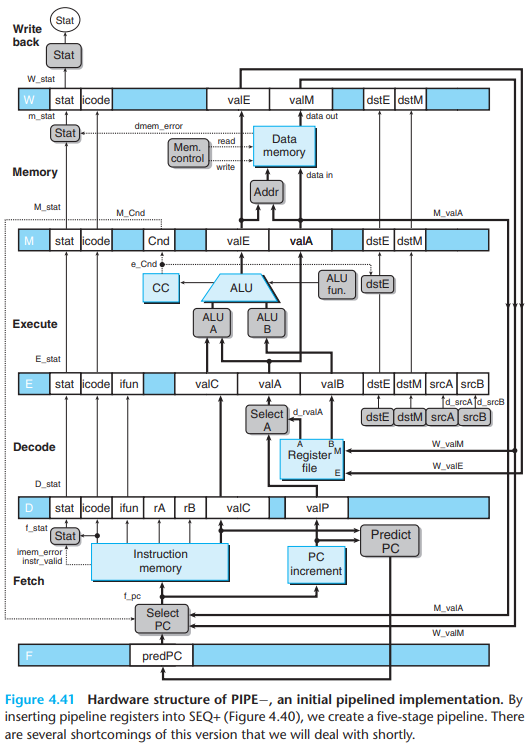
F holds a predicted value of the program counter.
D holds information about the most recently fetched instruction for processing by the decode stage.
E holds information about the most recently decoded instruction and the values read from the register file for processing by the execute stage.
M holds the results of the most recently executed instruction for processing by the memory stage. It also holds information about branch conditions and branch targets for processing conditional jumps.
W supply the computed results to the register file for writing and the return address to the PC selection logic when completing a
retinstruction.
Since normal program flow goes from top to bottom of a listing, we preserve this ordering by having the pipeline flow go from bottom to top.
3.Rearranging and Relabeling Signals
\(a.\)Some name reference
We use uppercase suffix to specified where data is stored. For example,
D_stat.We use lowercase suffix to specified which stage data has been computed. For example,
f_stat.
The uppercase letters refer to pipeline registers, while the lowercase letters refer to pipeline stages.
\(b.\)Details
The decode stages generate dstE and
dstM:
In SEQ+, we connect these signals directly to the address inputs of the register file write ports.
With PIPE−, these signals are directed to the register file only once they reach.
These are to make sure the write port address and data inputs hold values from the same instruction.
The "Select A" block generates the value
valAfor the pipeline register E by choosing eithervalPfrom pipeline register D or the value read from the A port of the register file. This block is included to reduce the amount of state that must be carried forward to pipeline registers E and M.- This is because only
callinstruction requiresvalPin the memory stage, onlyjumpinstruction requiresvalPin the execute stage(when the jump isn't taken). None of these instructions requires a value read from the register file.
- This is because only
4.Next PC Prediction
\(a.\)Branch prediction
When we fetch a conditional branch instruction, to decide which branch to take, we try to predict the next value of the PC.
For conditional jumps, if we predict that a jump will be taken, the PC will be
valC(computed by the PC incrementer).If we predict that it won't be taken, the PC will be
valP(from the fetch instruction).
There are several prediction strategies:
Always Taken.
Never Taken.
Backward Taken, Forward Not Taken. That is, branches to lower addresses than the next instruction will be taken, while those to higher addresses will not be taken. This strategy stems from the fact that loops are closed by backward branches and loops are generally executed multiple times.
We simply use "Always Taken" for branch prediction.
the block labeled "Predict PC" chooses either valP or
valC. This value is stored in pipeline register
F as the predicted value of the program counter.
\(b.\)ret
For ret instruction, we don't use any prediction.
Instead, we will simply hold off processing any more
instructions until the ret instruction passes through the
write-back stage.
5.Pipeline Hazards
When the dependencies referred before have the potential to cause an erroneous computation by the pipeline, they are called hazards. Hazards can be classified as either data hazards or control hazards.
\(a.\)Stalling
One very general technique for avoiding hazards involves stalling, where the processor holds back one or more instructions in the pipeline until the hazard condition no longer holds.
- Our processor can avoid data hazards by holding back an instruction in the decode stage until the instructions generating its source operands have passed through the write-back stage.
In holding back the addq instruction in the decode
stage, we must also hold back the halt instruction
following it in the fetch stage. We can do this by
keeping the program counter at a fixed value, so that
the halt instruction will be fetched repeatedly until the stall has
completed.
During the processing of addq, to perform the
stalling, we inject a bubble, which is a
dynamically generated nop instruction, into the
execute stage.
\(b.\)Forwarding
\(i.\)Forwarding process
Rather than stalling until the write has completed, it can simply pass the value that is about to be written to pipeline register E as the source operand. This technique of passing a result value directly from one pipeline stage to an earlier one is commonly known as data forwarding:
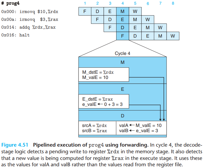
For forwarding, we can pass the newly computed values from the execute stage to the decode stage.
The decode-stage logic detects a pending write to register
%rdxin the memory stage, and also that the value being computed by the ALU in the execute stage will later be written to register%rax.It can use the value in the memory stage(signal
M_valE) for operandvalA. It can also use the ALU output(signale_valE) for operandvalB.
Forwarding can also be used with values read from the memory and destined for write port M:
From the memory stage, we can forward the value that has just been read from the data memory(signal
m_valM).From the write-back stage, we can forward the pending write to port M(signal
W_valM).
This gives a total of five different forwarding
sources(e_valE, m_valM, M_valE,
W_valM, and W_valE) and two different
forwarding destinations (valA and valB).
The following figure shows the structure of PIPE that can handle data hazards by forwarding. We can see that the values from the five forwarding sources are fed back to the two blocks labeled 'Sel+Fwd A" and "Fwd B" in the decode stage.
- The block labeled "Sel+Fwd A" combines the role of the block labeled "Select A" in PIPE with the forwarding logic.
\(ii.\)Forwarding judgement
Associated with every value that will be written back to the register file is the destination register ID. The logic can compare these IDs with the source register IDs srcA and srcB to detect a case for forwarding.
\(c.\)Load/Use hazards
One class of data hazards cannot be handled purely by forwarding is called load/use hazards:
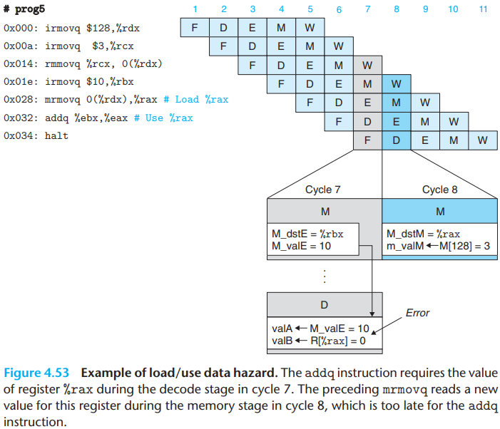
The addq instruction requires the value of the
register in cycle 7, but it is not generated by the
mrmovq instruction until cycle 8. In order to "forward"
from the mrmovq to the addq, the
forwarding logic would have to make the value go backward in time(or no
register will store our desired value)!
We can avoid a load/use data hazard with a combination of stalling and forwarding:
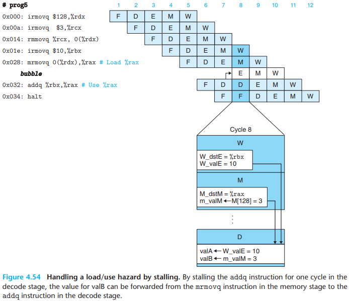
This technique is called load interlock. Since only load interlocks reduce the pipeline throughput, we can nearly achieve our throughput goal of issuing one new instruction on every clock cycle.
\(d.\)Avoiding control hazards
Control hazards arise when the processor cannot reliably determine the address of the next instruction based on the current instruction in the fetch stage.
\(i.\)ret
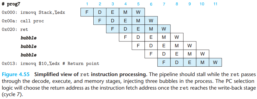
While the
retinstruction passes through the decode, execute, and memory stages, the pipeline cannot do any useful activity.Once the
retinstruction reaches the write-back stage, the PC selection logic will set the program counter to the return address, and therefore the fetch stage will fetch theirmovqinstruction at the return point(address 0x013).
\(ii\)Jump instruction
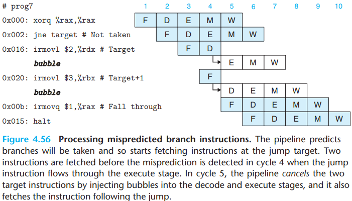
By the time the branch logic detects that the jump should not be taken during cycle 4, two instructions have been fetched that should not continue being executed.
Neither of these instructions has caused a change in the programmer-visible state. So the pipeline can simply cancel (sometimes called instruction squashing) the two misfetched instructions by injecting bubbles into the decode and execute stages on the following cycle while also fetching the instruction following the jump instruction.
6.Exception Handling
\(a.\)Several exception subleties
It is possible to have exceptions triggered by multiple instructions simultaneously.
- For example, we could have a
haltinstruction in the fetch stage, and the data memory could report an out-of-bounds data address for the instruction in the memory stage.
- For example, we could have a
When an instruction is first fetched and begins execution, causes an exception, and later is canceled due to a mispredicted branch. But we want to avoid rasing the exception.
It's possible for an instruction following one causing an exception to alter some part of the state before the excepting instruction completes.
- Take the assembly program below as an example, The exception of
pushq %raxis detected in memory stage, while theaddq %rax, %raxhas reached execute stage, and has already cause the condition codes to be set to new values(and otherstat):
- Take the assembly program below as an example, The exception of
1 | irmovq $1,%rax |
\(b.\)Handling exception
When an exception occurs in one or more stages of a pipeline, the information is simply stored in the status fields of the pipeline registers. The event has no effect on the flow of instructions in the pipeline until an excepting instruction reaches the final pipeline stage, except to disable any updating of the programmer-visible state.
For the first problem, we are guaranteed that the first instruction encountering an exception will arrive first in the write-back stage, at which point program execution can stop and the status code in pipeline register W can be recorded as the program status.
For the second problem, if some instruction is fetched but later canceled, any exception status information about the instruction gets canceled as well.
For the third problem, no instruction following one that causes an exception can alter the programmer-visible state.
7.PIPE Stage Implementation
\(a.\)PC selection and Fetch stage
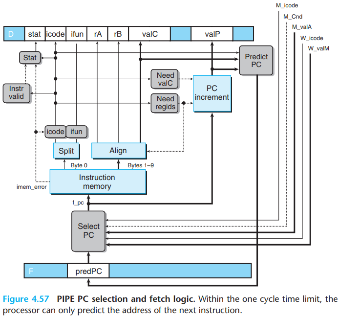
The hardware units for reading the instruction from memory and for extracting the different instruction fields are the same as those we considered for SEQ.
The PC selection logic chooses between three program counter sources:
For mispredicted branches, The value of
valP(indicating the address of the following instruction) is read from pipeline register M(signalM_valA).For
retinstruction, the return address is read from pipeline register W(signalW_valM).All other cases use the predicted value of the PC, stored in pipeline register F (signal
F_predPC)
1 | word f_pc = [ |
- The PC prediction logic chooses
valCfor the fetched instruction when it is either a call or a jump, andvalPotherwise:
1 | word f_predPC = [ |
Unlike in SEQ, we must split the computation of the instruction status into two parts:
In the fetch stage, we can test for a memory error due to an out-of-range instruction address, and we can detect an illegal instruction or a
haltinstruction.Detecting an invalid data address must be deferred to the memory stage.
\(b.\)Decode and Write-back stages
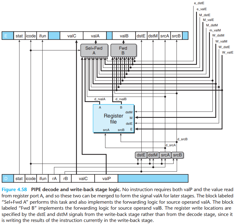
The register IDs supplied to the write ports come from the write-back stage(signals
W_dstEandW_dstM), rather than from the decode stage. This is to ensure that the final result is written back to the specified register only after the instruction has actually completed all operations, including memory access and execution.The block labeled "Sel+Fwd A" serves two roles: It merges the
valPsignal into thevalAsignal for later stages in order to reduce the amount of state in the pipeline register. It also implements the forwarding logic for source operandvalA.Only the
calland jump instructions need the value ofvalPin later stages, and these instructions do not need the value read from the A port of the register file.- This selection is controlled by the
icodesignal for this stage. When signalD_icodematches the instruction code for eithercallorjXX, this block should selectD_valPas it output.
- This selection is controlled by the
there are five different forwarding sources, each with a data word and a destination register ID:

If none of the forwarding conditions hold, the
block should select d_rvalA, the value read from register
port A, as its output.
The overall HCL description for the d_valA is as
below:
1 | word d_valA = [ |
The priority given to the five forwarding sources in the above HCL code is very important. This priority is determined in the HCL code by the order in which the five destination register IDs are tested.
To imitate this behavior, our pipelined implementation should always give priority to the forwarding source in the earliest pipeline stage, since it holds the latest instruction in the program sequence setting the register.
In previous part, we know that the overall processor status
Stat is computed by a block based on the status value:

Since pipeline register W holds the state of the most recently completed instruction, it is natural to use this value as an indication of the overall processor status. The only special case to consider is when there is a bubble in the write-back stage. This is part of normal operation, and so we want the status code to be AOK for this case as well:
1 | word Stat = [ |
\(c.\)Execute stage
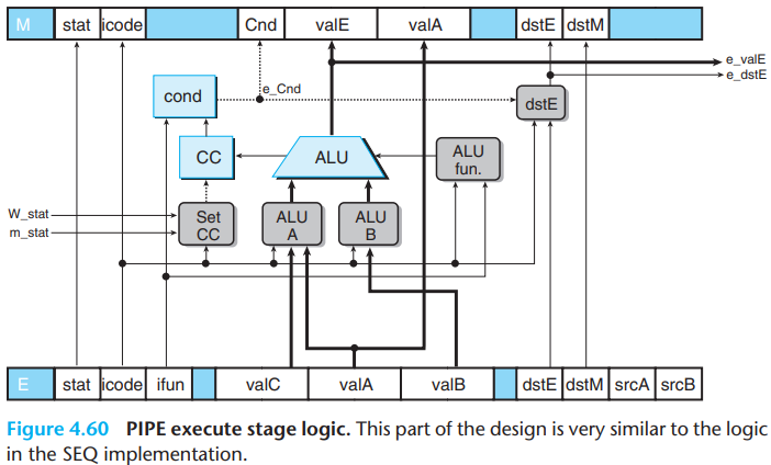
The logic labeled "Set CC", which determines whether or not
to update the condition codes, has signals m_stat
and W_stat as inputs. These signals are used to detect
cases where an instruction causing an exception is passing through later
pipeline stages, and therefore any updating of the condition
codes should be suppressed.
We need to ensure that the impact of the exception instruction is dealt with first to avoid incorrect barcode updates, so we suppress the condition codes.
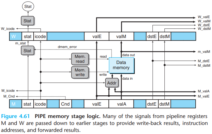
\(d.\)Memory stage
8.Pipeline Control Logic
\(a.\)Desired handling of special control cases
Implement the pipeline flow requires detecting the hazard condition, keeping pipeline registers F and D fixed, and injecting a bubble into the execute stage.
- The pipeline holds back an instruction in the decode stage by keeping pipeline register D in a fixed state. It should also keep pipeline register F in a fixed state, so that the next instruction will be fetched a second time.
\(i.\)ret
The figure below provides a detailed view of the processing of the
ret instruction for the example program:
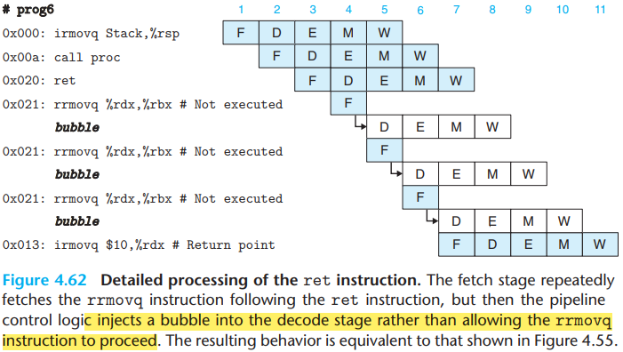
- The fetch stage stalls, causing the
rrmovqinstruction to be fetched but then replaced by a bubble in the decode stage.
\(ii.\)Mispredicted branch
When a mispredicted branch occurs, the control logic injects bubbles into the decode and execute stages on the next cycle, causing the two incorrectly fetched instructions to be canceled. On the same cycle, the pipeline reads the correct instruction into the fetch stage.
For an instruction that causes an exception, to make the pipeline implementation matches the desired ISA behaviour:
We record the status of each instruction by the status code
stat, and continue fetching, decoding, and executing instructions as if nothing were amiss.As the excepting instruction reaches the memory stage, we take steps to prevent later instructions from modifying the programmer-visible state by:
disabling the setting of condition codes by instructions in the execute stage,
injecting bubbles into the memory stage to disable any writing to the data memory,
stalling the write-back stage when it has an excepting instruction, thus bringing the pipeline to a halt.
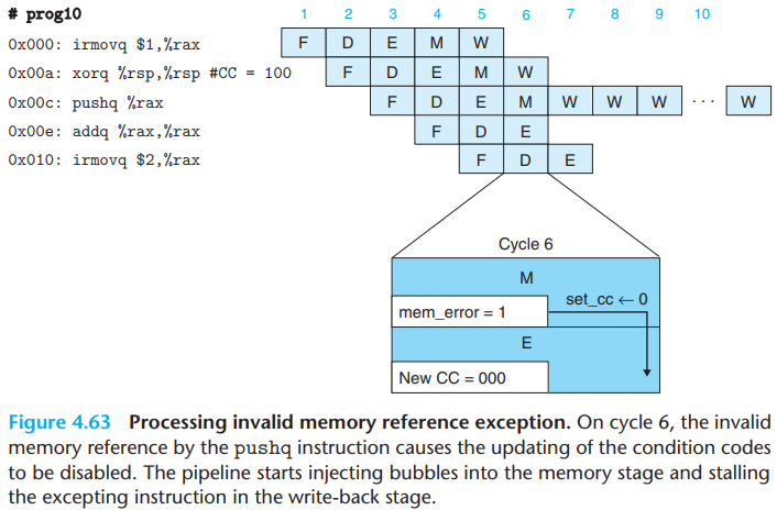
- We disable the setting of condition codes when an excepting
instruction is in the memory or write-back stage(by examining the
signals
m_statandW_statand then setting the signalset_ccto zero)
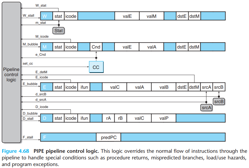
\(b.\)Detecting special control conditions
The following figure give expressions describing the conditions under which the three special cases arise:
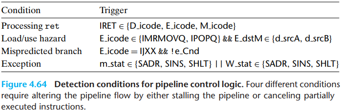
Detecting a
retinstruction involves checking the instruction codes of the instructions in the decode, execute, and memory stages.Detecting a load/use hazard involves checking the instruction type(
mrmovqorpopq) of the instruction in the execute stage and comparing its destination register with the source registers of the instruction in the decode stage.The pipeline control logic should detect a mispredicted branch while the jump instruction is in the execute stage, so that it can set up the conditions required to recover from the misprediction as the instruction enters the memory stage.
\(c.\)Pipeline control mechanisms
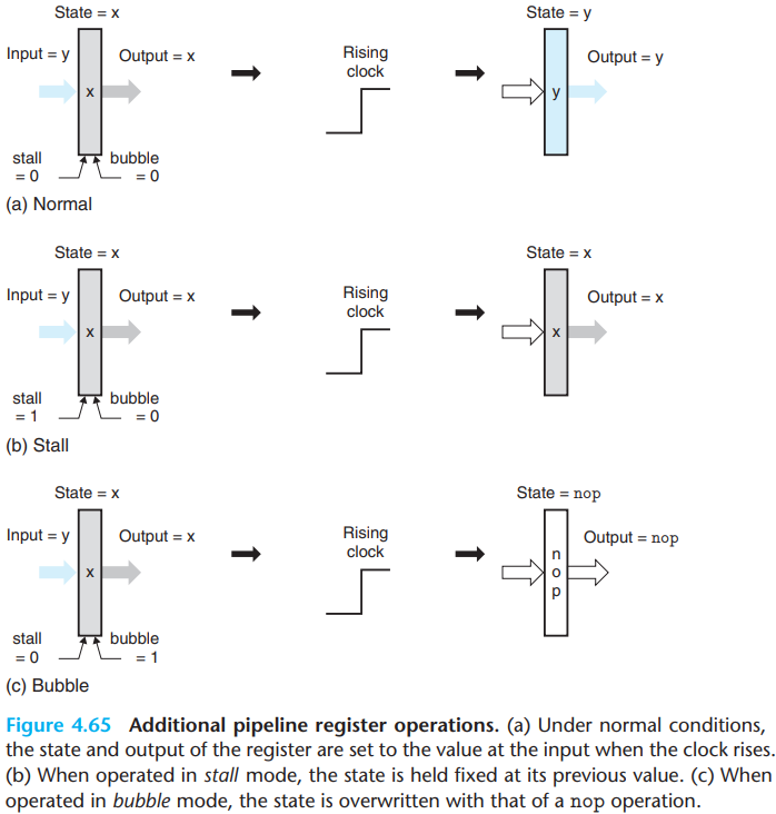
- When the bubble signal is set to 1, the state of the register will be set to some fixed reset configuration, giving a state equivalent to that of a nop instruction.
\(d.\)Control logic implementation
- Pipeline register F must be stalled for either a load/use hazard or
a
retinstruction:
1 | bool F_stall = |
Pipeline register E must be set to bubble for a load/use hazard or for a mispredicted branch:
1 | bool E_bubble = |
Pipeline register D must be stalled for a load/use hazard:
1 | bool D_stall = |
Pipeline register D must be set to bubble for a mispredicted branch
or a ret instruction. However, it should not inject a
bubble when there is a load/use hazard in combination with a
ret instruction:
1 | bool D_bubble = |
Pipeline register E must be set to bubble for a load/use hazard or for a mispredicted branch:
1 | bool E_bubble = |
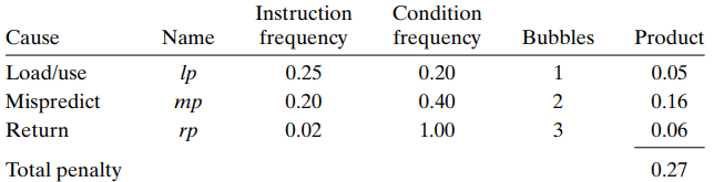
9.Performance Analysis
We measure the overall performance by computing an estimate of the average number of clock cycles PIPE would require per instruction it executes, a measure known as the CPI (for "cycles per instruction").
- If the stage processes a total of \(C_i\) instructions and \(C_b\) bubbles, then the processor has required around \(C_i+C_b\) total clock cycles to execute \(C_i\) instructions, and we can calculate the CPI as follows:
\[ CPI={ {C_i+C_b} \over C_i}=1.0+ {C_b \over C_i} \]
We can analyze the total penalty like below:
9.Multicycle Instructions
In a more complete instruction set, we would also need to implement instructions requiring more complex operations such as integer multiplication and division and floating-point operations. However, these operations require more than 1 cycle, so they need to be computed specially.
We can design a functional unit for performing integer multiplication and division, and another for performing floating-point operations.
As an instruction enters the decode stage, it can be issued to the special unit. While the unit performs the operation, the pipeline continues processing other instructions.
Typically, the floating-point unit is itself pipelined, and thus multiple operations can execute concurrently in the main pipeline and in the different units
The operations of the different units must be synchronized to avoid incorrect behavior. Often, different forms of forwarding are used to convey results from one part of the system to other parts, just as we saw between the different stages of PIPE.