5.7.Understanding Modern Processors
\(5.7.\)Understanding Modern Processors
1.Overall Operation
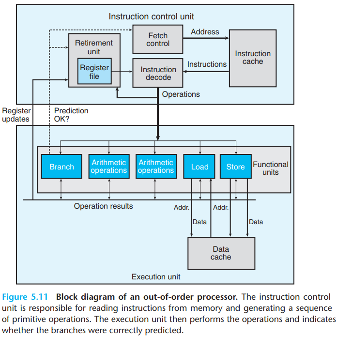
The overall design of the superscalar processor(meaning that they can perform multiple operations on every clock cycle and out of order) has two main parts:
The instruction control unit(ICU), which is responsible for reading a sequence of instructions from memory and generating from these a set of primitive operations to perform on program data.
The execution unit(EU), which then executes these operations.
\(a.\)ICU
THe ICU reads the instructions from an instruction cache.
When a program hits a branch, processors perform branch prediction. If it later determines that the branch was predicted incorrectly, it resets the state to that at the branch point and begins fetching and executing instructions in the other direction.
- The block labeled "Fetch control" incorporates branch prediction to perform the task of determining which instructions to fetch.
The instruction decoding logic takes the actual program instructions and converts them into a set of primitive operations(micro-operations).
- The decoding allows a division of labor among a set of dedicated hardware units, which then allows parallelism.
For example, the instruction addq %rax,%rdx will be
decoded as three operations: one to load a value from memory into the
processor, one to add the loaded value to the value in register
%eax, and one to store the result back to memory.
The retirement unit keeps track of the ongoing processing and makes sure that it obeys the sequential semantics of the machine-level program.
As an instruction is decoded, information about it is placed into a first-in, first-out queue. The information of an instruction remains in the queue until one of two outcomes occurs:
Once the operations for the instruction have completed and any branch points leading to this instruction are confirmed as having been correctly predicted, the instruction can be retired, with any updates to the program registers being made.
If some branch point leading to this instruction was mispredicted, the instruction will be flushed, discarding any results that may have been computed.
\(b.\)EU
The EU receives operations from the instruction fetch unit. These operations are dispatched to a set of functional units that perform the actual operations.
Reading and writing memory is implemented by the load and store units. Both the load unit and store unit have an adder to perform address computations. They access memory via a data cache.
With speculative execution, the operations are evaluated, but the final results are not stored in the program registers or data memory until the processor can be certain that these instructions should actually have been executed.
Branch operations are sent to the EU to determine whether or not they were predicted correctly.
If the prediction was incorrect, the EU will discard the results that have been computed beyond the branch point. It will also signal the branch unit that the prediction was incorrect and indicate the correct branch destination.
The result of operations is exchanged among the EU. The control of the communication of operands is called register renaming.
When an instruction that updates register r is decoded, a tag t is generated giving a unique identifier to the result of the operation. An entry \((r,t)\) is added to a table maintaining the association between program register r and tag t for an operation that will update this register.
When a subsequent instruction using register r as an operand is decoded, the operation sent to the execution unit will contain t as the source for the operand value.
When some execution unit completes the first operation, it generates a result \((v,t)\), indicating that the operation with tag t produced value v. Any operation waiting for t as a source will then use v as the source value
This form of data forwarding enables values to be forwarded without being written to and read from the register file, so that the second operation to begin as soon as the first has completed.
2.Functional Unit Performance
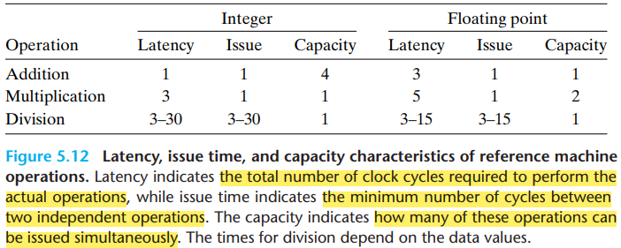
The addition and multiplication operations all have issue times of 1, meaning that on each clock cycle, the processor can start a new one of these operations. They are called fully pipelined.
The divider isn't pipelined-its issue time equals its latency. It means that the divider must perform a complete division before it can begin a new one.
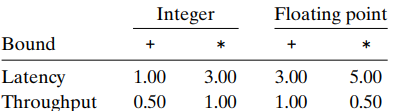
The latency bound gives a minimum value for the CPE for any function that must perform the combining operation in a strict sequence.
The throughput bound gives a minimum bound for the CPE based on the maximum rate at which the functional units can produce results.
3.An Abstract Model of Processor Operation
We will take combine4 as an example. First, let's see
the CPE measurements of the program:
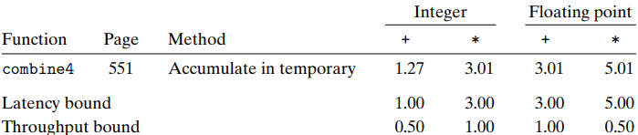
- The performance of these functions is dictated by the latency of the sum or product computation being performed. Computing the product or sum of \(n\) elements requires around \(L \cdot n+K\) clock cycles, where \(L\) is the latency of the combining operation and \(K\) represents the overhead of calling the function and initiating and terminating the loop. The CPE is therefore \(L+{K \over n}\), which is close to \(L\) when \(n\) is large.
\(a.\)Data-flow graphs
First take a look at the assembly codes of
combine4:
1 | # Inner loop of combine4. data_t = double, OP = * |
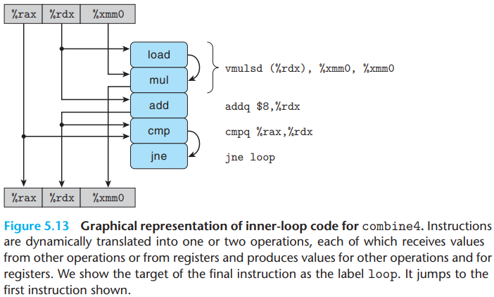
The graphical representation of inner-loop code for
combine4 is as below:
And the data-flow representation of \(n\) iterations in the inner loop is as below:
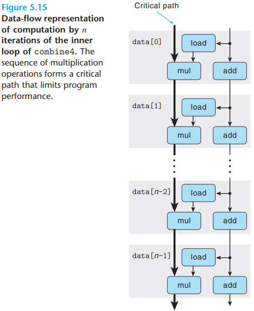
We can see that the program has two chains of data dependencies,
corresponding to the updating of program values acc and
data+i with operations mul and
add, respectively. And since the left chain is the
longest, it will form a critical path, requiring \(5n\) cycles to execute.
The figure shows that when executing the function, the
floating-point multiplier becomes the limiting resource. The
other operations required during the loop—manipulating and testing
pointer value data+i and reading data from memory—proceed
in parallel with the multiplication.
\(b.\)Other factors
The critical paths in a data-flow representation provide only a lower bound on how many cycles a program will require. Other factors can also limit performance, including the total number of functional units available and the number of data values that can be passed among the functional units on any given step.
\(e.g.\)(CPE analysis)Illustrate why the CPE of the former program is 5.00 while the latter is 8.00:
1 | double poly(double a[], double x, long degree) { |
1 | /* Apply Horner's method */ |
\(solution:\)The CPE of the
poly is decided by the instruction
result += a[i] * xpwr; and
xpwr = x * xpwr;.
For result += a[i] * xpwr, after the first sequential
operation of 8 cycle, the + and * can be
executed in pipeline. So the CPE is $ $.
The analysis for polyh is the same. The
result = a[i] + x * result cannot be executed in
pipeline(because both LHS and RHS contain result), so the
CPE is 5+3=8.