5.3.CPU
\(5.3.\)Central Processing Unit
1.Abstraction
We can view CPU as a 16-bit processor, designed to:
Execute the current instruction.
- This turns the static code into reality.
Figure out which instruction to execute next.
2.Hack CPU interface
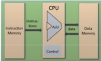
- CPU is connected both to the instruction memory and to the data memory.
here is the specific input and output connections of the CPU:
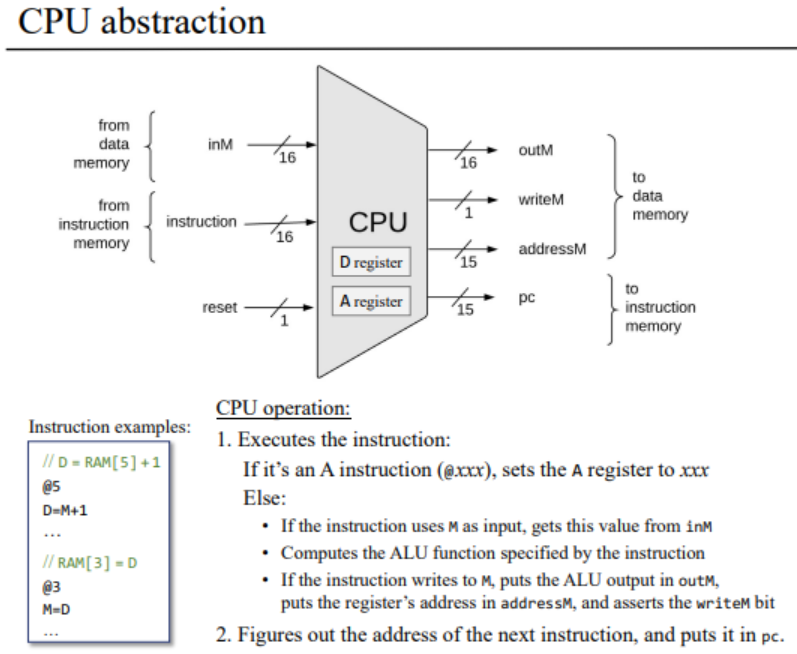
We have three inputs coming from three completely different sources.
A 16-bit data value, which is the value of the currently selected data memory register. This is the value CPU is going to operate on.
A 16-bit instruction value, which is the value of the selected instruction memory register.
- Remember that at any given point of time, there is always a selected register in the instruction memory, and a selected memory register in the data memory. So always something comes into the CPU.
A 1-bit input, which we decide to call the reset.
On the right hand side we see the outputs of ALU:
The ALU specifies 3 different things to write something to the data memory:
- outM: What we want to write.
- writeM: A load bit that enables the data memory to write operations.
- address: Where do we want to write it.
- pc: It holds the address of the next instruction that has to be fetched and executed in the next cycle of this computer.
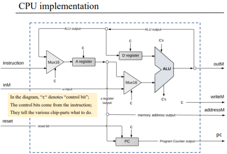
3.CPU implementation
The whole CPU hardware diagram is as below:
\(a.\)A instruction
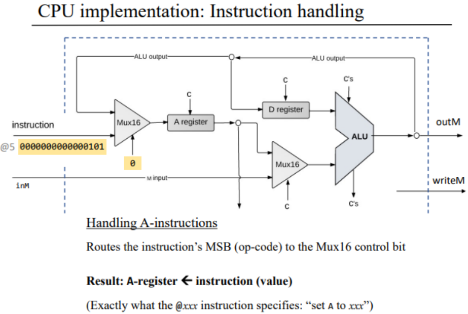
This section contains:
- A register called A.
- An A-instruction input that connects to this register through a multiplexer.
We see that this instruction seeks to load the value
3001 into a register. In order to carry out this
instruction, the CPU do:
- Decode the instruction into op-code + 15-bit value.
- Noticing that it is a A instruction, CPU stores the 15-bit value in the A-register.
- Take the output of A register and admit it outside.
\(b.\) C instruction
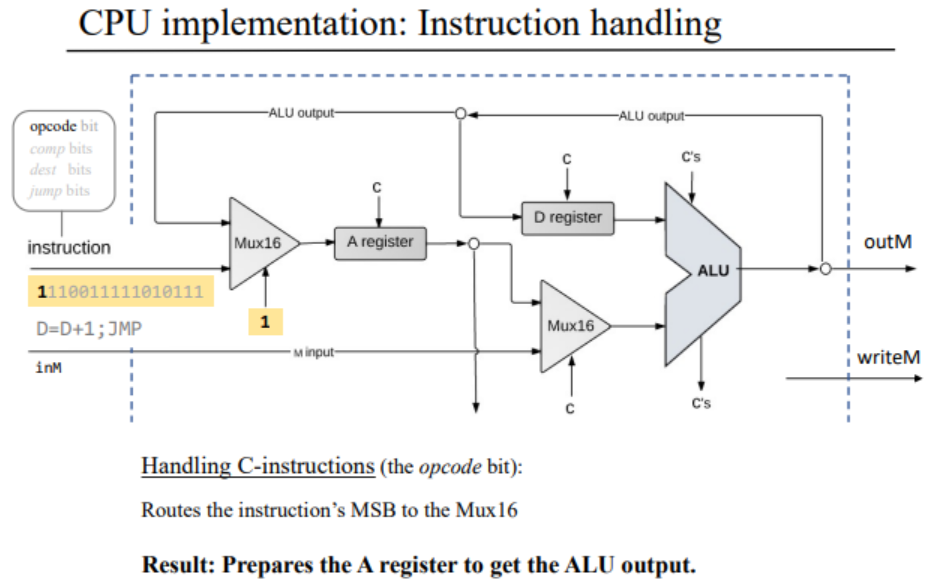
This section contains:
- A register.
- C instruction.
Others is the same as above.
Say we want to gain an A instruction, we can use the Mux16:
- If the instruction input is with an op-code
0, we choose the instruction input. - Otherwise, we choose the ALU input.
- If the instruction input is with an op-code
\(c.\)ALU Operation
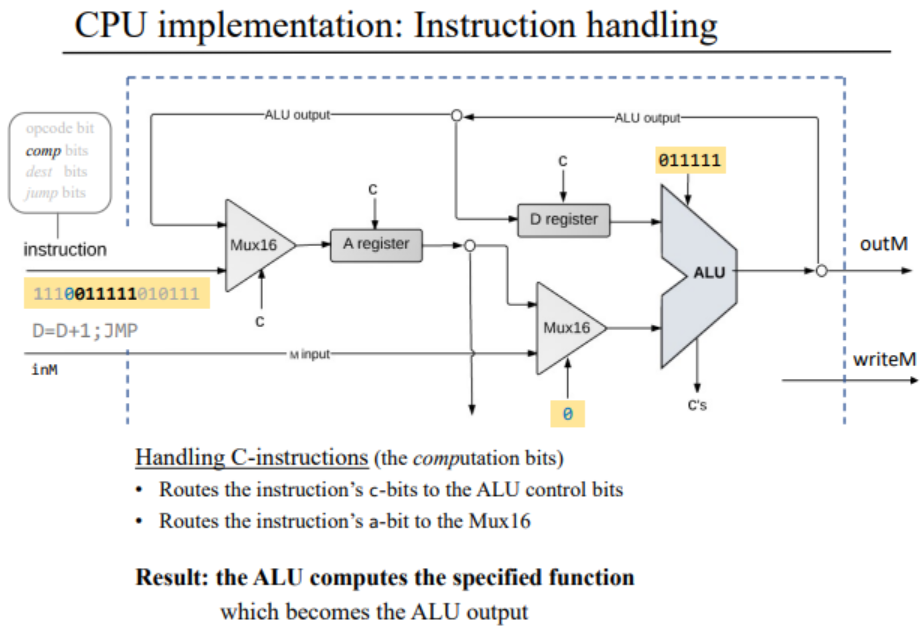
The inputs of ALU come from:
D register
Either the value of A register or selected memory register.
Multiplexer takes care of this decision, and the control bit of it is one of the bits in the instruction.
- The CPU designer has to choose this bit, and then ALU gets the correct input.
ALU also has 6 control bits taken together to tell or specify the ALU which operation we want to carry out.
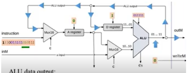
The output of ALU is simultaneously fed into:
D register
A register
M register
- It goes through a Multiplexer.
The same ALU is fanned out into 3 different places, so we have the same ALU output knocking on three different doors. The programmer has to decide which door to be opened. The decision is made by next field of bits —— destination bits:
- We have 3 destination bits, which decide whether or not open the D register, A register, M register and the data memory to accept the ALU output.
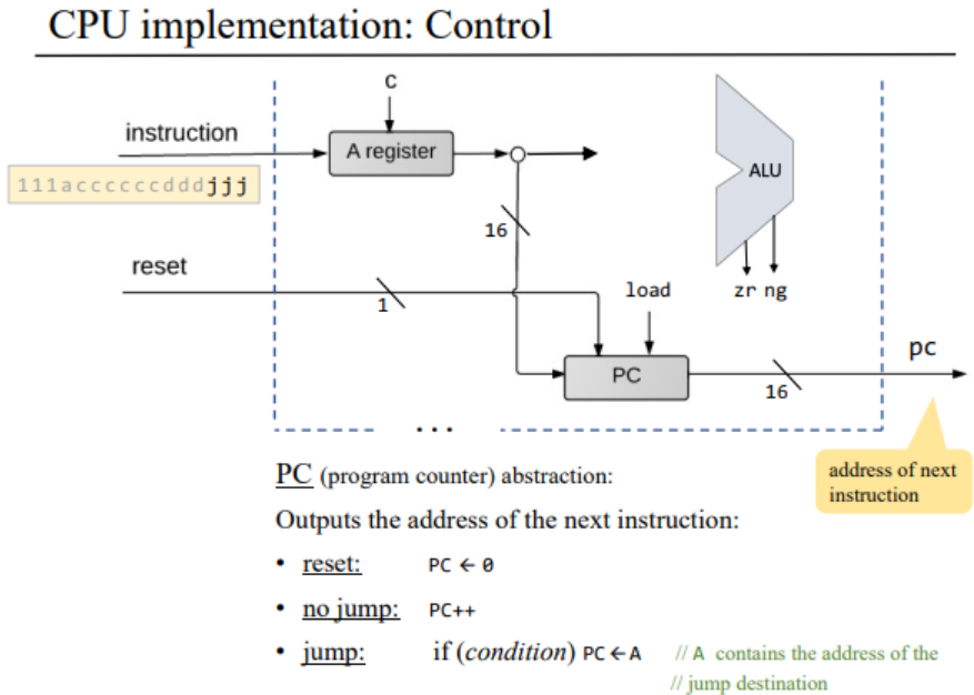
\(d.\)Control abstraction
The computer is loaded with some program, when you push
reset, the program starts running.
In our previous chapter, we know that the last three bits of the
instruction is jump bits, which a 1 represents
unconditional goto. CPU realizes this functionality by
program counter
\(i.\)PC abstraction
Emits the address of the next instruction:
- To start / restart the program's execution:
PC = 0(for we want to execute the first instruction of the program). - no jump:
PC++ - unconditional
goto:PC = A - conditional
goto: if truePC = AelsePC++
- To start / restart the program's execution:
\(ii.\)Control implementation
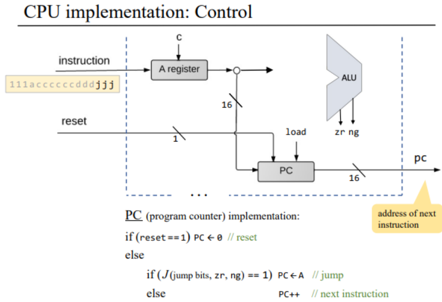
if
reset == 1,PC=0else
We have to look at the jump bits and simultaneously look at the ALU output to decide if we want to carry out the jump.
load = f(jump bits, ALU control outputs)- if
load == 1,PC = A - else
PC++
- if