3.2.触发器
\(3.2.\)Flip Flops
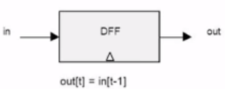
1.Clocked Data Flip Flops
To implement the sequential logic, we need an element that remember one bit of information from \(t-1\) so that it can be used at time \(t\). It remembers by "flipping" between the possible states. Such gates that can flip between two states are called Flip Flop:
Take the clock below as example:
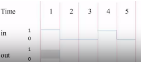
- At time 1, we don't exactly know what our output will be because we haven't specified what happened in the previous time unit. So we just don't know what the output is.
- At time 2, the output is exactly what the input was in time 1,
1. - ......
2.Sequential logic implementation
Here is a generic paradigm of how we're going to build all our logic in the computer, and it's going to be a combination of remembering information via this basic D flip flops and then manipulating them using combinatorial logics:
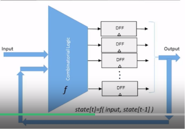
- We have an array of D flip flops which basically compromise all of our memory in the system.
- Their output is going to be fed into some combinatorial logic together with the new input that you get in this time unit.
- All of this is going to change the state that we have in the D flip flop for the next time unit.
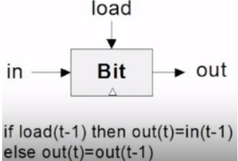
3.1-bit Register
The 1-bit Register has these functionalities:
- Once we take the load bit and put the 1 into it, we want it remember the input bit at that time.
- When the load bit goes down to 0 we want it keep remembering the last input that was loaded into it for infinity, until a new load operation is performed.
Notice that there are two source into the DFF: one is the output
from the previous stage, the other is the new input. Whether source to
be chosen is decided by load, so we may use a
Mux to solve this:
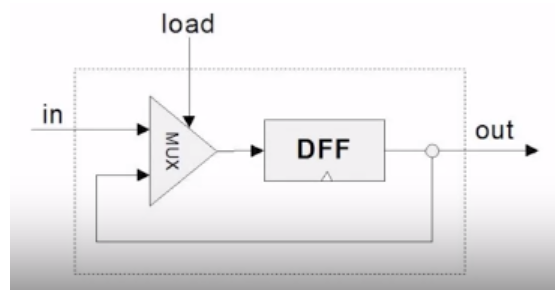
- The DFF serves the purpose of storing and maintaining the previous input value in this process. When the load bit is set to 1, the DFF stores the input value and holds it unchanged until the next load operation. When the load bit is 0, the DFF maintains the value from the previous load and continues to output this value in the next time unit until a new load operation occurs. Therefore, the DFF is essentially used to remember and sustain the state of the input value.
- The final output is determined by the multiplexer (Mux). The DFF is responsible for storing the previously loaded value and sending it to the multiplexer based on the state of the load bit. The multiplexer selects whether to accept the new input value or the previously loaded value based on the load bit's status, and then outputs the selected value.